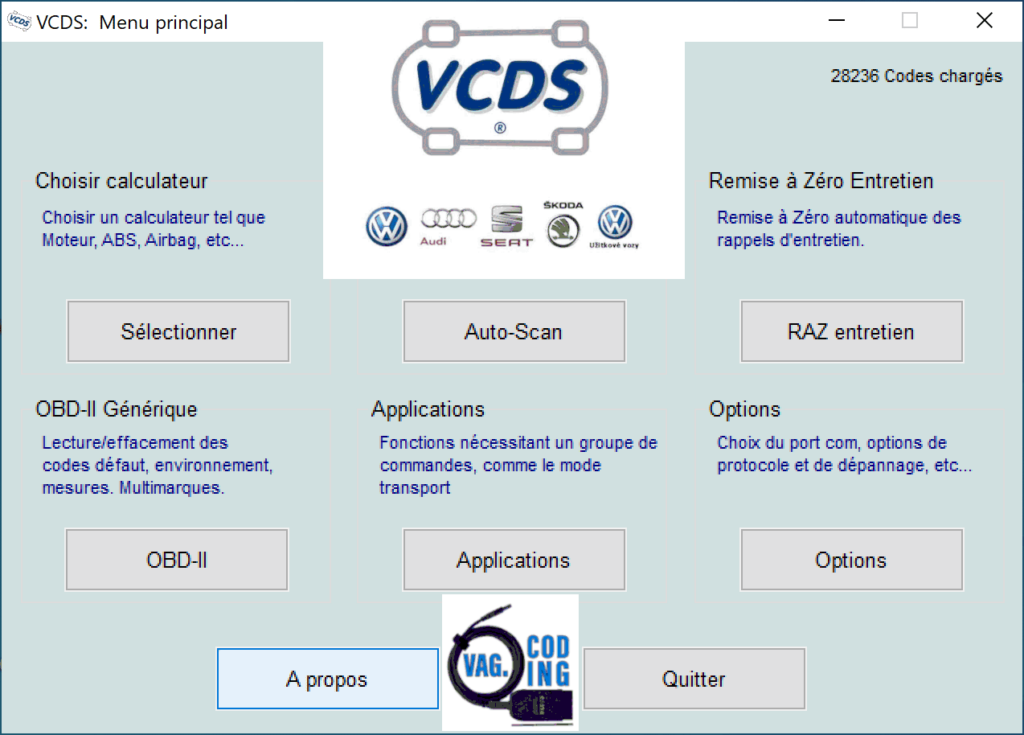
1 – VCDS stands for VAG-COM Diagnostic System:
It’s diagnostic software designed primarily for Volkswagen, Audi, Seat and Skoda vehicles from Ross-Tech.
It allows you to personalize your vehicle, read fault codes and code and parameterize ECUs.
The software also has a generic OBD2 mode: this function can be used to read the fault memory of any make of vehicle.
-> VCDS software installation and configuration tutorial
-> VCDS: How do I make a backup before coding?
2 – VCDS: What is it?
VCDS (VAG-COM Diagnostic System) is a powerful diagnostic software package used to carry out analyses and adjustments on Volkswagen Audi Group (VAG) vehicles. The coding function is one of the key features offered by VCDS.
Coding in VCDS makes it possible to modify the software parameters of the various electronic control modules present in a VAG vehicle. These modules control various systems such as the engine, transmission, on-board electronics, air conditioning, safety devices and many others.
Using the coding function, users can adjust and personalize certain behaviors or functionalities of the vehicle’s electronic components. This can include enabling certain hidden options, adding new functionality, disabling specific features, or modifying settings to adapt the vehicle to particular needs.
Thanks to this feature, experienced users can make precise modifications to meet specific driver requests or to solve certain problems, while respecting the manufacturer’s original specifications.
However, it is important to stress that coding requires a thorough understanding of the vehicle’s electronic systems, as well as advanced technical skills. Incorrect manipulation of the parameters can have negative consequences on the vehicle’s operation. It is therefore advisable to consult qualified professionals or reliable resources before making any changes using the VCDS coding function.
3 – VAGCOM coding and VCDS tutorials
Information on VAGCOM and VCDS software
VAGCOM is a diagnostic cable for Volkswagen, Audi, Seat and Skoda vehicles. It connects a laptop computer to the vehicle’s OBD-II socket to read fault codes and perform diagnostics on various vehicle systems, such as the engine, transmission, brakes, air conditioning and more.
VCDS (VAG-COM Diagnostic System) is diagnostic software for use with the VAGCOM cable. It allows you to read fault codes and view live data from vehicle sensors and components, reset fault codes, set parameters for certain systems and even make coding changes for certain components.
Users can use VCDS to perform diagnostics on Volkswagen, Audi, Seat and Skoda vehicles of various years and models, including recent models with autonomous driving technology. The software can also be used to solve common problems, such as engine fault codes, transmission problems and braking issues. It is also useful for mechanics and technicians to carry out more advanced repairs without going to the dealership.
Here are some of its key features and functions:
- Connexion au véhicule, lecture des codes défaut :
- VCDS connects to your vehicle’s Electronic Control Unit (ECU), enabling it to read and clear fault codes.
- Advanced diagnostics:
- It offers advanced diagnostics, including the ability to monitor your vehicle’s parameters in real time (access to measurement groups, control of LOGS based on engine mapping (setpoint vs. sensor readings)).
- Customization: VCDS also allows you to customize certain functions on your vehicle, such as daytime running lights, door locks, etc.
- this is known as activating hidden options or VAGCOM CODING
- Procédures embarquées
- The VCDS software includes a whole range of on-board procedures for testing sensors and actuators to check that everything is in order on a vehicle.
- An invaluable maintenance aid
- Reset maintenance intervals
- Oil temperature check as part of a DSG gearbox oil change
- Release the parking brake when replacing the rear brake pads.
- Compatibility: Compatible with a wide range of VAG vehicles.
Many modifications are possible with the VagCom and VCDS software. Coding is often used to add or modify certain parameters on your car. Beware, these modifications are sometimes complicated, but thanks to all the tutorials on our VAG Coding site, they’re becoming more accessible, even if 00001 means nothing to you. Thanks to the explanations below, found on the Internet, you’ll finally be able to understand how to code, and what coding changes mean when you check or uncheck an option in the VCDS software. What are the consequences, and how does the software affect the calculators? Why 00 and not 01? Bit, byte, byte?
When using VCDS software and VAGCOM cable, always remember to make backups of modified elements.
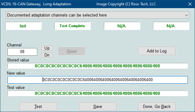
4 – Adaptation (10)
The Adapt function can be used to modify certain values and/or parameters in control modules that support it.
Warning!
- You should refer to your particular car’s factory repair manual (or other documented procedure) before “playing” with the adapter function. However, many of the available tuning channels are completely undocumented! At the very least, make a note of the original values; recording an automatic analysis is an excellent way of doing this. There’s no other way to “undo” or restore the original values if what you’re trying to do doesn’t work.
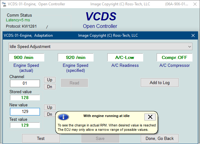
You can use the [Up] and [Dn] buttons next to Channel to scroll through the 255 possible channels, or you can manually enter a channel number and click [Read] . If a channel exists, VCDS will show you the stored value. If a channel doesn’t exist, the stored value will be displayed as “N/A”. Other data that the controller may or may not be sending will be decoded and displayed in the four display fields at the top of the screen.
Once you’ve reached a channel you’re interested in, you can use the [Up] and [Dn] buttons next to New Value to modify and progressively test the value. Or you can enter a new value directly, which will then prompt you to click [Test] . This will tell the controller to temporarily use the new value so that you can evaluate its effects.
When you are satisfied with the effect of a new value, you can store it permanently in the controller by clicking on [Save] .
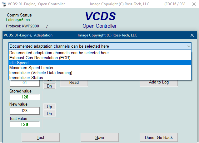
Label files can support adaptation channel values and descriptions. A help graphic can be displayed in a tooltip. For control modules that have a label file with adaptation information, a drop-down menu may also be available, allowing you to select from the supported functions:
UDS: For controllers using the UDS/ODX/ASAM protocol, the drop-down menu MUST be used, as traditional adaptation channels do not apply. The name of each channel must coincide with the factory identifiers of various data objects, such as IDEnnnnnn. The search box can be used to filter the Channel drop-down menu to display only items containing your search term. The [Clear] button resets the search box. In Adaptation for UDS controllers, WSC, Importer and Equipment numbers can be entered if required by the controller.
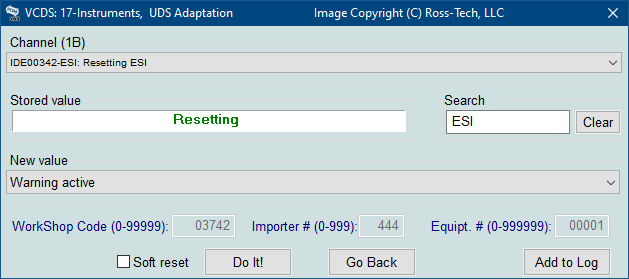
Software reset can be checked to prompt the control module to “reboot” itself once the change has been made. In some cases, this (or an ignition cycle) is required in some UDS modules before changes take effect.
If you simply wish to record a snapshot of the current readings in each group, click on [Add to log] . This will save the results on your PC, usually in your C:\Ross-Tech\VCDS\Logs directory.
Remarks:
- Channel 00 is a special case. Performing a [Save] on channel 00 resets all adaptation values to their original default values. This only works on controllers that support this function; check your factory repair manual to see if this procedure applies to every controller in your vehicle.
- Some engine and immobilizer controllers will require a valid connection before you can [Test] or [Save] adaptation values.
- Values entered with [Test] but not saved will persist until the controller is switched off.
Long adaptation is a subset of the adaptation function and is used/necessary (for example) to balance the fuel injectors on common-rail TDI engines (such as the BKN). It is also used in the CAN gateway of new vehicles such as the A5, as illustrated here :
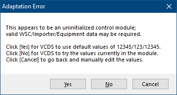
If an uninitialized control module warning appears, this means that one or more workshop, importer or equipment code numbers are all zeros. Since some modules will not allow you to record adaptation values unless non-zero numbers are in one or all of these fields, VCDS will display this error when it thinks this might be the case. In most cases, you need to click [Yes] to allow VCDS to enter 12345/123/12345 in these fields. If you click on [No] , VCDS will try to use the values currently stored in the module, even if they are all zeros. If you click on [Cancel] , VCDS will allow you to manually enter the values for each of these fields.
Click [Done, Go Back] to return to the controller opening function screen.
05 – Coding (07)
Representation of values in Decimal, Binary and Hexadecimal
Many modifications are possible with Vag-Com / VCDS. Coding is often used to add or modify certain parameters. Thanks to the explanations below, you’ll finally be able to understand how to code, and the meaning of coding modifications by checking or unchecking an option.
The binary
Presentation
Binary is the counting mode that uses base 2 instead of base 10. It’s used by computers, because machines can only compare two values: 1s and 0s.
I told you about ranks (units, tens, hundreds…), and in binary we use the word “bit” (a contraction of “binary-digit”, meaning simply “binary rank”).
For example, the base 2 number “10011” is spread over 5 bits.
Where it gets complicated is that, in binary, each rank can only take on two values (it could take on ten in decimal). So, as soon as the rank reaches its second – highest – value, you change rank. In binary, a rank starts at 0 and ends at 1.
You can see that each bit represents a power of 2, just as each rank in base 10 is a power of 10.
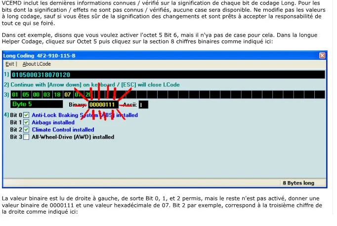
Example Binary in VCDS (1: bit checked, 0: bit unchecked):
| bit7 | bit6 | bit5 | bit4 | bit3 | bit2 | bit1 | bit0 |
| 0 | 0 | 0 | 1 | 1 | 1 | 0 | 0 |
Hexadecimal
Presentation
After binary, here comes another base: the hexadecimal system, which works in base 16.
If you’ve followed this far, you’ll have guessed that 16 different characters are needed to represent each of the 16 values.
And then, with bewildering originality, in hexadecimal, the characters are 0, 1, 2 etc. up to 9, as well as A, B, C, D, E and F.
As you can see, A in hexadecimal is worth 10 in decimal, B is worth 11, … and F is worth 15.
In hexadecimal, the rank change is made at F. Thus E+1 = F and F+1 = 10 (i.e. “one-zero”).
More complicated: F+B = 1A.
In electronics and computing, the basis is a system with two stable states, the binary, the simplest representation is a switch, it can be on or off, there is a voltage present or not.
The control of flashing lights could be represented by 10101010 a succession of 1’s and 0’s at a rate of 0.5 seconds interval.
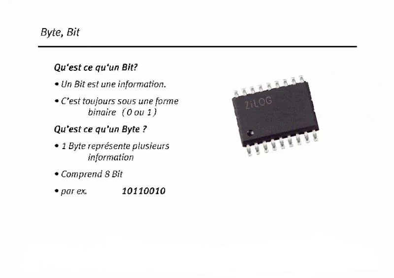
This basic information is called a bit(binarydigit) and is grouped together in blocks of 8 to form an octet or byte.
All computers work on this principle and when you buy a 32- or 64-bit Windows operating system, it actually works in groups of 4×8 bits or 8×8 bits.
It won’t be long before there are microprocessors working in 19- or 43-bit versions.
Let’s take the case of the power plant: it has a set of 30 bytes for its coding, which amounts to having a sequence of 240 bits 0 or 1. This is tedious to retranscribe and generates errors, so to reduce this string a little and make it more readable, we use hexadecimal notation, which represents 8 bits by 2 alphanumeric characters from 0 to 9 or from A to F.
digits 0 to 9 retain their value, 10 is written A, 11 is written B, 12 is written C, 13 is written D, 14 is written E and 15 is written F.
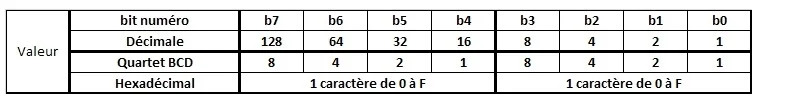
The 8 bits that make up a byte are written from right to left, with the rightmost bit (b0) having the decimal value 1 and each bit on the left having double the value of its right-hand neighbor.
The relationship between decimal, binary and hexadecimal values is shown in this table.
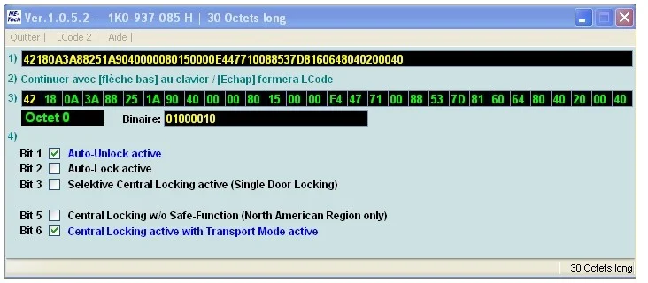
Let’s take the coding of the power plant, byte 0 is this one:
The values are as follows:
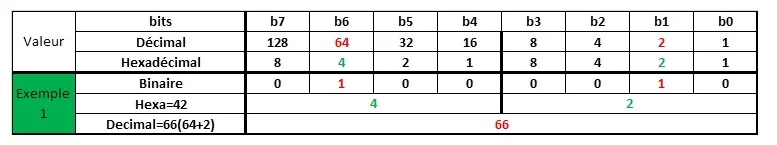
For this example of byte 0, the value can be written in any of these three forms:
In binary: 01000010, in practice very often separated into quartets (0100 0010) for readability and ease of conversion to hexadecimal.
In hexadecimal: 42
In decimal: 66
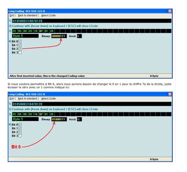
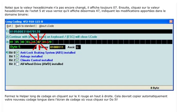
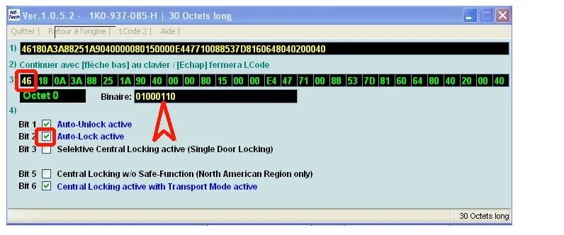
To modify the coding and activate automatic door locking when driving, bit 2 must be checked.
This automatically changes the hexadecimal value from 42 to 46 and the binary value from 01000010 to 01000110.
It is therefore possible to modify the coding in three different ways, for this example:
1- Check bit 2.
2- Directly modify the hexadecimal value from 42 to 46.
3- Directly modify the binary value from 01000010 to 01000110.
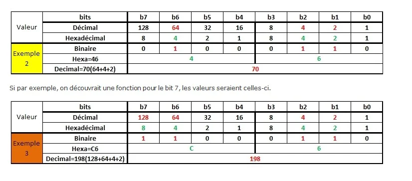
The values are as follows:
PRACTICE: learn how to modify or code a calculator :