
Purpose: Displays the Climatronic Hidden Menu.
Displaying instantaneous digital speed? it’s possible! No need to use your VCDS VAG-COM cable for this tutorial.
What’s it for?
In the hidden Audi Climatronic menu, you can easily access secret diagnostic readings such as battery voltage, car speed, engine rpm, sensor readings, system DTC codes and much more.
Audi Climatronic single-zone hidden menu procedure
To display some of the car’s operating parameters on the air-conditioning display:
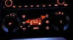
- Simultaneously press the air recirculation button and the upward ventilation button.
- The display shows “1C” (channel 1 is the default).
- Use the temperature change knob to select the desired function. Press “+” to access the upper channel and “-” to access the lower channel.
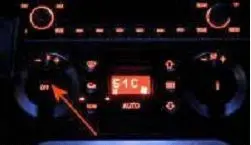
- For example, for real-time engine oil temperature, you need to display channel 51 (51C on the screen).
- Confirm the function by pressing the air recirculation button.
- The selected channel’s information is then displayed on the climate control screen.


List of hidden menu channels
| 1 | System error |
| 2 | Virtual sensor value |
| 3 | Inside console sensor value |
| 4 | Outside temperature value – water tank sensor |
| 5 | Outside temperature value – bumper sensor |
| 6 | Lower supply sensor value |
| 7 | Front air sensor value |
| 8 | Display check |
| 9 | Digital value of temperature valve return potentiometer |
| 10 | Digital temperature valve setpoint |
| 11 | Digital value of air conditioning valve return potentiometer |
| 12 | Digital air conditioning valve setpoint |
| 13 | Digital value of foot valve/defrost return potentiometer |
| 14 | Digital foot valve/defrost setpoint |
| 15 | Digital value of supply air damper return potentiometer |
| 16 | Digital supply air damper setpoint |
| 17 | Speed in km/h |
| 18 | Ventilation voltage value (Volts) |
| 19 | Ventilation voltage setpoint (Volts) |
| 20 | Compressor voltage value (Volts) |
| 21 | Number of very low voltage events (non-volatile) |
| 22 | High-pressure switch status |
| 23 | Number of high-pressure events (volatile) |
| 24 | Number of high-pressure events (non-volatile) |
| 25 | A/D value Kick-Down switch |
| 26 | A/D value warm indicator light |
| 27 | Engine speed |
| 28 | Compressor speed |
| 29 | Coding |
| 30 | Software version |
| 31 | Software index |
| 32 | Error counter potentiometer temperature valve |
| 33 | Meter errors potentiometer air conditioning valve |
| 34 | Meter errors potentiometer feet/defrost valve |
| 35 | Error meter potentiometer supply air damper |
| 36 | Cold stop temperature valve |
| 37 | Hot stop temperature valve |
| 38 | Air conditioning damper stop closed |
| 39 | Air conditioning damper stop open |
| 40 | Foot valve/defrost stop |
| 41 | Foot stop foot valve/defrost |
| 42 | Supply air damper stop open |
| 43 | Supply air damper stop closed |
| 44 | Rolling cycle counter |
| 45 | Calculated indoor temperature (Ninc) |
| 46 | Filtered outdoor temperature (°C) |
| 47 | Unfiltered outdoor temperature (°C) |
| 48 | ECOR |
| 49 | Coolant temperature |
| 50 | Stopping time in minutes |
| 51 | Engine oil temperature in °C |
| 52 | Compressor stop conditions |
| 53 | Display active electrical outputs: compressor, room air valve, water valve |
| 54 | Control indication number |
| 55 | Outside temperature in °C |
| 56 | Virtual indoor sensor °C |
| 57 | Indoor console sensor °C |
| 58 | Water tank temperature °C |
| 59 | Bumper temperature °C |
| 60 | Lower supply sensor temperature |
| 61 | Temperature of front air sensor |
| 62 | Solar intensity W/m-1 |
| 63 | Filtered solar intensity W/m-1 |
| 64 | Delta ventilation increase |
| 65 | Delta transition air conditioning dampers |
| 66 | Cadence time /1.6 sec |
| 67 | Cold start correction |
| 68 | Maximum setpoint P and I components |
| 69 | Blower sensor value feet (cnts) |
| 70 | Foot blow sensor setpoint (cnts) |
| 71 | Difference (Epsilon) |
| 72 | Share (+ heating / – cooling) |