
Purpose: Displays the Climatronic Hidden Menu.
Displaying instantaneous digital speed? it’s possible! No need to use your VCDS VAG-COM cable for this tutorial.
What’s it for?
In the hidden Audi Climatronic menu, you can easily access secret diagnostic readings such as battery voltage, car speed, engine rpm, sensor readings, system DTC codes and much more.
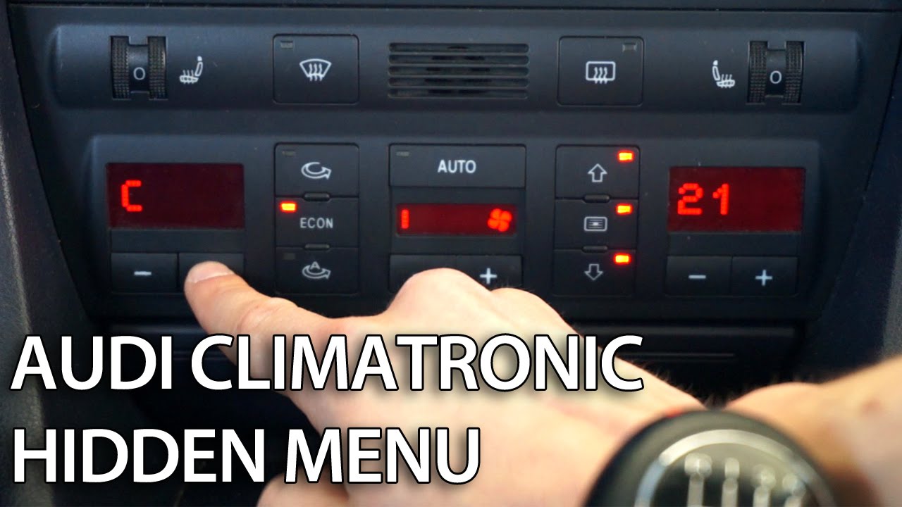
Audi Climatronic single-zone hidden menu procedure
- Switch on the ignition and wait a few seconds for the Climatronic system to start. You can also switch on the engine.
- Press and hold the air recirculation button and the windshield ventilation button.
- Use the temperature buttons on the left to select the channel.
- Press the air recirculation button to read the value of the selected channel.
- Press the recirculation button again to return to channel selection.
- Switch off the ignition to exit the Audi A6 C5 Climatronic hidden diagnostics menu.
List of hidden menu channels
- 1 – CTD
- 2 – Indoor temperature sensor value, head (G 86)
- 3 – In-dash temperature sensor value (G 56)
- 4 – fresh air intake temperature sensor value (G 89)
- 5 – value of outside air temperature sensor (G 17), front
- 6 – outdoor air temperature sensor value
- 7 – Fresh air blower temperature sensor value (G 109)
- 8 – Potentiometer value for temperature-controlled flap motor (G 92)
- 9 – temperature control authority flap value
- 10 – specified value of temperature control ruse
- 11 – central potentiometer value for flap motor (G 112)
- 12 – specified value of center flap
- 13 – Potentiometer value for low-cost/arrow motor (G 114)
- 14 – specified value of Footwell/Defroster Flap
- 15 – Potentiometer value for air motor (G 113)
- 16 – specified airflow damper value
- 17 – speed (km/h)
- 18 – Air blower voltage (volts)
- 19 – specified fresh air blower voltage (volts)
- 20 – A/C compressor voltage (volts)
- 21 – Low-voltage event counter
- 22 – A/C high-pressure switch cycle status (F 118)
- 23 – A/C high-pressure switch cycles (F 118)
- 24 – switch cycles, no absolute fluctuation
- 25 – kick-Down Switch
- 26 – Cooler temperature warning light (ECT)
- 27 – Motor speed (RPM)
- 29 – A/C compressor speed (RPM)
- 30 – SW version
- 32 – Malfunction counter, temperature control flap
- 33 – Malfunction counter, central flap
- 34 – Malfunction counter, Footwell/Defroster Flap
- 35 – malfunction counter, airflow map
- 36 – cold stop, temperature regulator (G 92)
- 37 – hot stop, temperature regulator, temperature flap motor (G 92), maximum stop
- 38 – cold stop, motorized flap-type power unit (G 112)
- 39 – Hot stop, central potentiometer for flap motor (G 112)
- 40 – cold stop, Footwell motor/flap over potentiometer (G114)
- 41 – hot stop, foot/arrow flap motor potentiometer (G114)
- 42 – cold stop, air level Engine map (G 113)
- 43 – hot shutdown, air plane for air flow map motor (G 113)
- 44 – Vehicle operating cycle counter
- 45 – calculated indoor temperature
- 46 – outside temperature, filtered, for control
- 47 – outdoor temperature in degrees C
- 48 – outdoor temperature
- 49 – operating countermeasure for speed signal
- 50 – rest time (in minutes)
- 51 – motor Cooler Temperature
- 52 – Graphic channel 1 – A/C compressor stop conditions are identified by illuminated segments of the “88.8” display.
- 53 – Graphic channel 2 – The electrical outputs of the climate system are identified by illuminated segments of the “88.8” display.
- 54 – Control features
- 55 – outdoor temperature for SIF/DIS
- 56 – temperature in degrees C, from indoor temperature sensor, in hairdresser (G 86)
- 57 – temperature in degrees C, from interior temperature sensor in instrument panel (G 56)
- 58 – temperature in degrees C, from fresh air intake pipe temperature sensor (G 89)
- 59 – temperature in degrees C, from outside air (ambient) Temperature sensor (G 17), front
- 60 – temperature in degrees C, from room temperature sensor at fresh air blower (G 109)
- 61 – software version
- 86 – Control display